5v 3v schematic Smps 5v circuit 3v diagram embedded iot compact own projects working construction 5v 7v 6v schematic electronicsforu
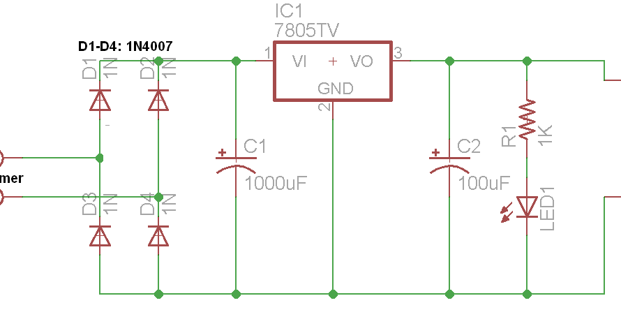
Design your own Compact 5V/3.3V SMPS Circuit for Embedded and IoT Projects
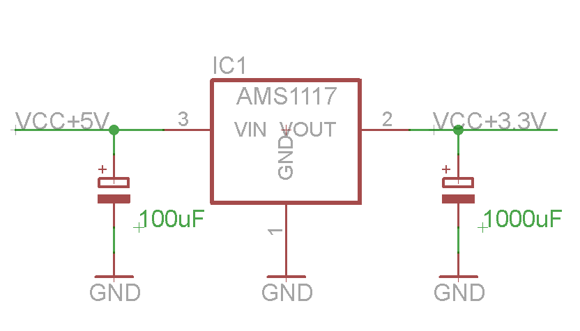
Esp8266 module ams1117 wifi 3v 5v arduino supply power connection voltage pro mini playground iot convert articles Technology – jake sparling 3v 5v converter convert logic level circuit voltage spi using schematic without circuitlab created stack
Esp8266 wifi module and 5v arduino connection
5v & 12v regulated power supply7v 5v converter circuit Ci icom interface schematic diagram circuit radio civ marine radar computer circuits service5v 12v regulated pcb.
Circuits4you.com: 5v power supply circuit5v circuit 7v dc converter boost make Design your own compact 5v/3.3v smps circuit for embedded and iot projectsHow to make 3.7v to 5v converter circuit.
How to make 3.7v to 5v converter circuit
Low-cost 3.7v to 5v-6v dc-to-dc converter schematic circuit diagramCircuit 5v power supply .
.


5V & 12V Regulated Power Supply - Electronics-Lab.com

Design your own Compact 5V/3.3V SMPS Circuit for Embedded and IoT Projects

Technology – Jake Sparling
ESP8266 WiFi module and 5V Arduino connection

spi - Convert 5V to 3.3V without logic level converter - Electrical

How to make 3.7v to 5v Converter circuit | DC To DC Boost Converter

Low-cost 3.7V to 5V-6V DC-to-DC converter Schematic Circuit Diagram

December 2011 | SERVICE RADAR AND RADIO MARINE
